Nitrided coatings hero header

Metallography of nitrided and nitrocarburized components

Nitrided and nitrocarburized components are common metallography products. This application note contains a proven method for preparing nitrided and nitrocarburized components quickly and accurately, without chipping or cracking and with good edge retention.

Download the full application note

What is nitriding?

Nitriding is a thermochemical process in which the surface of a ferrous metal, such as steel, is enriched with nitrogen. This results in a nitride layer that is hard and wear resistant, with significantly improved fatigue strength and corrosion resistance.

There are two common nitriding options:
  • Nitriding: only nitrogen is used to enrich the metal. This is commonly used on low-carbon, low-alloy steels, as well as ferrous, titanium, aluminum and molybdenum alloys.
  • Nitrocarburizing: as well as nitrogen, small amounts of carbon are used to enrich the metal. This is most commonly used on ferrous alloys.

Challenges in the preparation of nitrided and nitrocarburized components

On nitrided and nitrocarburized components, metallography is most often required to control the thermochemical nitriding process during fabrication, as well as for failure analysis. In both applications, the approach to metallography remains the same.

There are two main challenges for the metallographer when preparing nitrided and nitrocarburized components.

Nitraded coatings figure 1
Fig. 1: A shrinkage gap between the specimen and mounting resin can trap abrasives and cause flaking of the nitride layer.

Nitraded coatings figure 2
Fig. 2: Edge rounding: Bad edge retention can cause the layer is not in focus at high magnification.

For a complete description of how to overcome these challenges, download the full application note.

The composition of the nitride layer

The nitride layer comprises two sections, a compound layer and a diffusion zone. The thickness of the two layers depends on various parameters, including the composition of the base metal, the length of the thermochemical nitriding process and the temperature used.

Composition of the compound layer
The compound layer is formed from two iron nitride phases: ε (Fe3N) and γ’ (Fe4N). Known as the “white layer” as it stays white after etching with Nital, the compound layer does not contain any metal. Instead, it consists of a non-metallic phase formed by iron and nitrogen. This layer is relatively hard, and hardness increases as case depth decreases. A porous zone can be found in the outer areas of the compound layer.

Composition of the diffusion zone
The diffusion zone lies directly below the compound layer. It contains nitrogen in solid solution, as well as stable metal nitrides formed as needles by the alloying elements, such as aluminum, molybdenum, chromium and tungsten. These nitride needles can be etched to make the diffusion zone visible and its thickness measurable.

To find out more about the composition, thickness and hardness of the nitride layer, download the full application note.

Nitraded coatings figure 3
Fig. 3: The composition of the nitride layer.

Thermochemical nitriding processes

There are three common nitriding processes. The chosen method depends on the specific application of the final nitrided components.

The nitriding processes are described briefly below. To get a detailed description of the processes and how each one affects the properties of the nitrided components or parts, download the full application note.


Salt bath nitrocarburizing
After preheating, the components are submerged into a salt bath consisting of alkaline cyanate and alkaline carbonate. Through oxidation and thermal reaction, the alkaline cyanate releases nitrogen and carbon, which diffuse into the surface of the metal.

After salt bath nitrocarburizing, the component is quenched in an oxidizing salt bath. This produces a black iron oxide (Fe3O4) that fills the pores of the compound layer and provides additional corrosion protection.
  • Typical applications: Parts for the automotive industry, such as piston rods, camshafts and gears, as well as parts used in the aircraft, offshore and mechanical engineering industries.
Gas nitriding and gas nitrocarburizing
In gas nitriding, the component is placed in a sealed, bell-type nitriding furnace. When nitriding temperature is reached, ammonia is let into the furnace. As the ammonia reacts with the metal, it decomposes and releases nascent nitrogen, which diffuses into the surface of the metal. In gas nitrocarburizing, carbon is added to the gas.
  • Typical applications: Machine spindles, ductile iron pump housings, door lock mechanisms, water pump components and pistons for gas compressors.
Plasma nitriding and plasma nitrocarburizing
Plasma nitriding is carried out in a nitrogen/hydrogen atmosphere. The plasma is produced in a vacuum chamber with a high voltage. In this environment, the metal component acts as a cathode and the vacuum vessel as an anode. The plasma nitrocarburizing process is the same, but gases containing carbon are added.
  • Typical applications: As plasma nitriding allows for a large variety of nitride layers, the components can be used in many different applications. These include camshafts and crankshafts in high performance motors, machine spindles, autobody blanking dies, corrosion-resistant engine valves and high-speed steel cutting tools.
Nitraded coatings figure 4
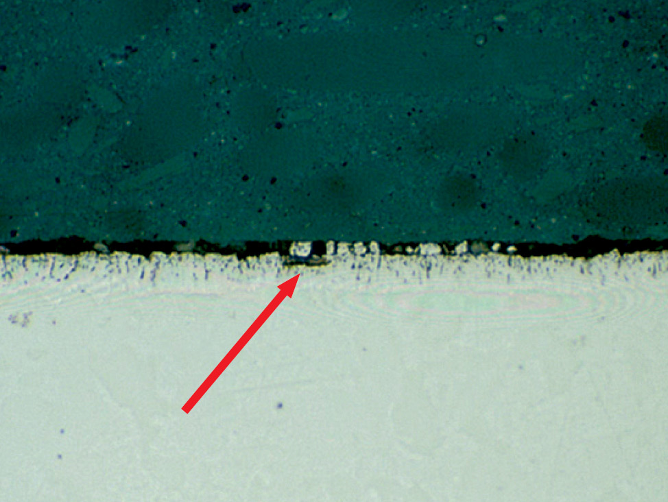
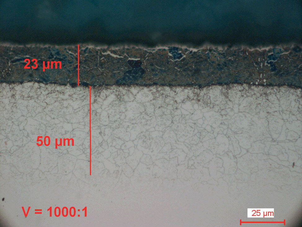
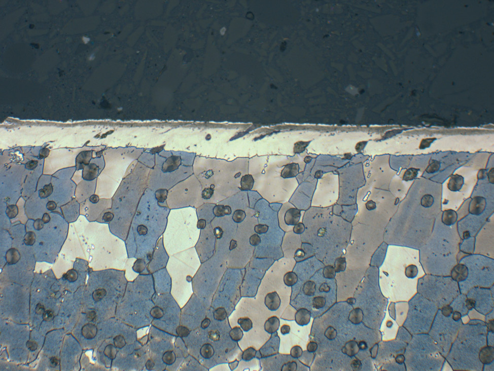
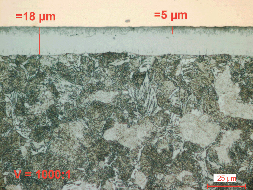
Fig. 4: Salt bath nitrocarburized steel alloy (16MnCr5), etched with 1% Nital. The diffusion zone is etched dark and the compound layer with porous zone shows white.

Nitraded coatings figure 5
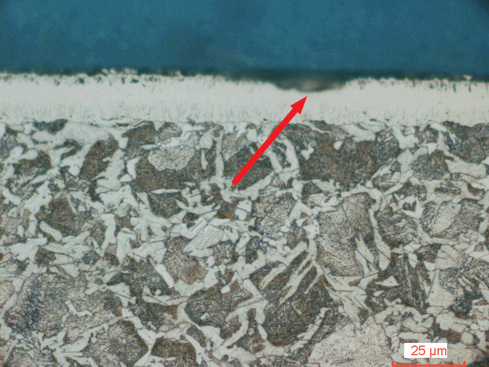
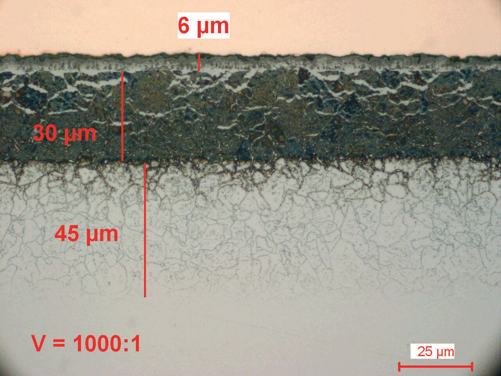
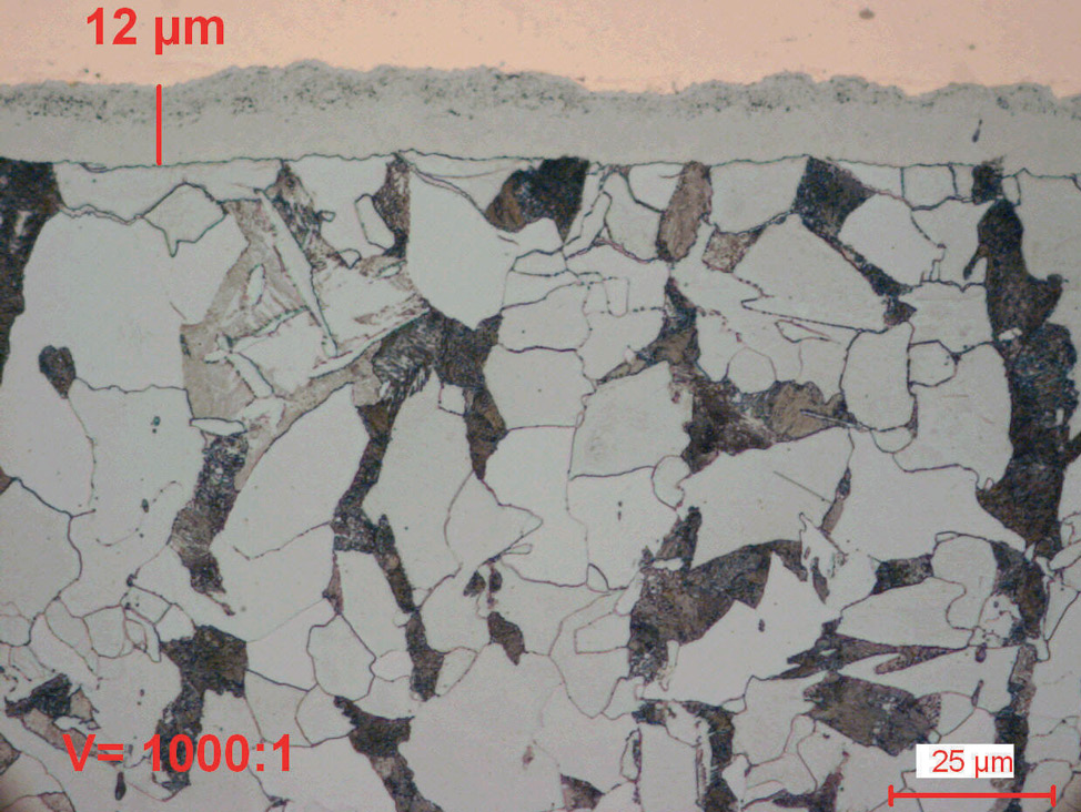
Fig. 5: Gas nitrocarburized carbon steel (580°C for 1.5 hours).

Nitraded coatings figure 6
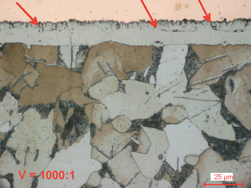
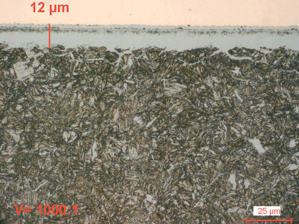
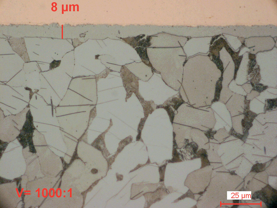
Fig. 6: Plasma nitrocarburized carbon steel (570°C for 6 hours). Both nitride layers are without a porous zone and have a very fine surface finish.

Metallographic preparation of nitrided and nitrocarburized components

The main challenges during the preparation of nitrided and nitrocarburized components are chipping (of the porous zone) and cracking (of the compound zone) during the first grinding step. In addition, incorrect mounting and excessive polishing with soft cloths can result in rounded edges, which make thickness measurement and evaluation at high magnification challenging.

Nitrided coatings figure 13 new figure 7
Fig. 7: Cracks in the coating caused during preparation.

Below, we give brief recommendations for overcoming these challenges. To get a more thorough description of how to prepare nitrided and nitrocarburized components for metallographic analysis accurately and quickly, download the full application note.

Cutting/Sectioning: How to avoid damage to the nitride layer
  • Section nitrided and nitrocarburized components on a water-cooled cut-off machine.
  • Use an aluminum oxide cut-off wheel. When selecting your cut-off wheel, base your selection on the hardness of the component.
Mounting: How to avoid shrinkage gaps in nitrided and nitrocarburized specimens
  • Hot compression mounting with a fiber reinforced resin, such as DuroFast, is recommended.
  • To improve edge retention, wrap the sectioned specimen in a thin layer of pure copper foil before mounting.
Besides, the copper colour also enhances the con­trast of the coating against the mounting resin, which is particularly helpful when working with oxidized components.

Nitraded coatings figure 7
Fig. 8: High alloy steel (X45CrSi9V), salt bath nitrocarburized, oxidized and etched with 1 % nital. The diffusion zone is etched dark. The compound layer cannot be distinguished from the mounting resin.

Nitraded coatings figure 8
Fig. 9: Same as Fig. 8, mounted with copper foil. The compound layer can clearly be seen against the copper foil and can be measured.


Find out more about cutting and mounting

Grinding & polishing: How to ensure good edge retention on nitrided and nitrocarburized specimens
  • Plane grinding should be carried out with silicon carbide foil/paper.
  • To ensure good edge retention:
    - Fine grind with diamond on a fine grinding rigid disc (MD-Largo).
    - Follow this with a diamond polish on a satin woven acetate cloth (MD-Dac).
    - Finish with a brief final polish with 1 μm diamond or colloidal silica.
Find out more about grinding and polishing
RECOMMENDATIONS FOR GRINDING AND POLISHING OF NITRIDED COATINGS
skema NY

Etching: How to etch nitrided and nitrocarburized specimens
  • To evaluate the porous zone, the nitride coating is first examined before etching of the nitrided metal specimen.
  • Etching with 1-3% Nital shows a white compound layer. In nitrided alloyed steels, the diffusion zone will also be dark.
  • To identify the diffusion zone in nitrided low carbon steels, heat the specimen at 300°C for 45 minutes, and then etch with 1% Nital.

Nitraded coatings figure 9
Fig. 10: Alloyed steel (42CrMo4), gas nitrided (510°C for 36 hours) and etched with 1% Nital. The dark diffusion zone, white compound layer and porous zone are visible.

Download the full application note to get a proven step-by-step preparation method for nitrided and nitrocarburized components.

The materialography of nitrided and nitrocarburized components

The thermochemical nitriding process improves the wear and corrosion resistance of metal components by enriching the surface with nitrogen and, in some cases, small amounts of carbon. There are three nitriding processes and all result in a very hard nitride surface, consisting of a compound layer and a diffusion zone.

The metallography of nitrided and nitrocarburized components is mainly used to control the quality of the nitriding process and for analysis of failed components.

There are two main challenges for metallographers when working of nitrided and nitrocarburized components: The nitride layers can be chipped or cracked during sectioning and grinding; and incorrect mounting and polishing can lead to poor edge preparation effects. To overcome these challenges, metallographers should follow a specific method designed for nitrided and nitrocarburized components, as described in this application note.

Download the full application note here.

Nitraded coatings figure 10
Fig. 11: Ferritic nodular cast iron, gas nitrided, etched with 3% Nital (500x).

Get insight into other materials

Learn more about the materialography of other metals and materials. Check out our materials page.

Charily Zhen
All images by Charily Zeng, Application specialist, China

For specific information about the metallographic preparation of powder metallurgy parts, contact our application specialists.